The foot pedal was being used so I ended up using the fancy pick and place machine.
Heated the board a little...
BEAUTIFUL! Actually two of my resistors are connected together but after looking at the diagram you know that this are connected regardless. In other words, no need to worry.
I skipped a couple of steps here, well, not really but I didn't include them in the documentation.
It is IMPORTANT to verify that all the components are solder correctly before connecting them to a computer, to power for that matter.
To test this grab a multimeter and verify that the grounds are connected to the grounds and nothing else. The same goes for the powers.
Even after doing this, I was still a little nervous so I actually used a power supply instead of my computer (to power it). It turned out that all the components were solder correctly but better to be safe.
Programing / Burning the bootloader
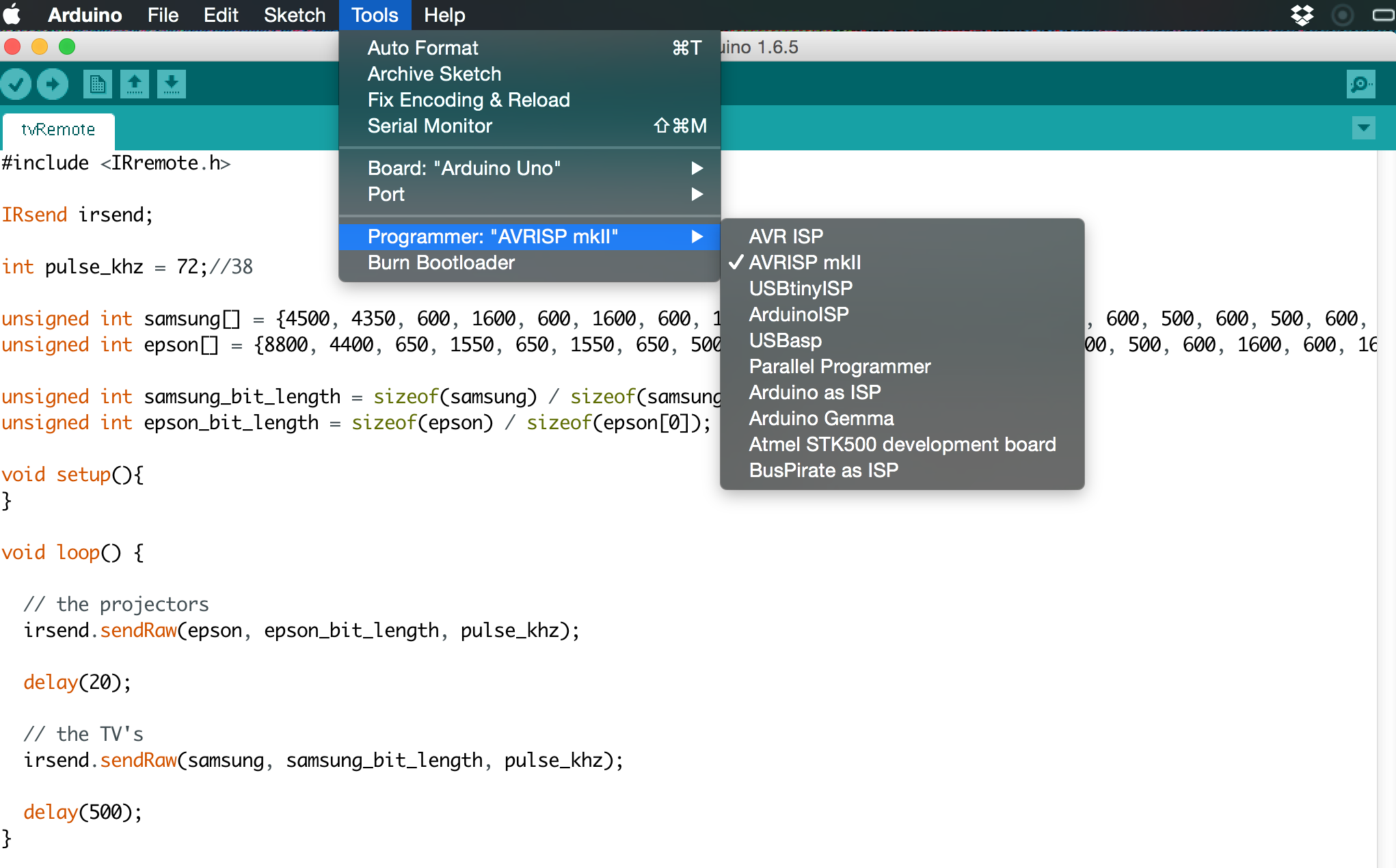
In this case I was using the AVRISP MKII to burn the bootloader and then to upload my sketch to the atmega.
There are a couple of tutorials on how to do so online but I found them a little confusing. The actual process is really simple.
First make sure the pogo pins are oriented in the right direction. The green LED should light up on the programer.
- Select the right Programer from the "Tools" menu.
- Click Burnbootloader
- Upload sketch using programer (⇧⌘U)

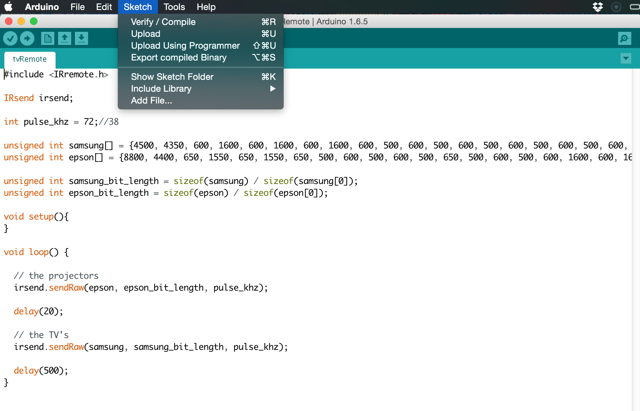
Note: I had to change the frequency variable on the code (pulse_khz) from 36 to 72. I think I had the wrong crystal so my code was running twice as fast. After some frustrating attempts I was able to turn the projector in the classroom off.